


On Apple's Making of Vision Pro
Manufacturing Mastery

Apple’s latest reveal is a feast for the eyes of anyone who works in manufacturing. It features nearly every kind of engineering discipline and method of fabrication beautifully orchestrated into a symphony of production automation.
Let’s dive in and break down some of the processes we’re seeing so you can more fully understand and appreciate this rare and truly exquisite look behind the curtain at one of the world’s greatest design companies.
Extrusions
It all begins with a stack of saw-cut extrusions. For the unfamiliar, extruding is a process that creates a part shaped by pushing material through a die with great force. It’s a terrific way to facilitate mass production by starting with your material closer to a finished shape than rectangular bar stock.

The most common types of extrusions are direct, indirect, and impact, though there are many more methods of forcing material through an extrusion die.

Direct extrusions are the most commonly used method and is likely what was used for this application. It typically requires more force than the other methods which can lead to uneven material flow and less consistent surface finish, but would be fine when you’re machining away every exterior surface anyway.
Indirect is better for parts requiring greater precision, requires less force than direct, and generally results in a more uniform product with better surface finish. I’d suspect that this method was used with the Apple watch considering the pride taken in demonstrating its uniformity in a prior video.
Impact extrusions were used on Apple’s older “trashcan” Mac Pro’s, in which an aluminum slug is placed in a die and impacted by a mandrel under great force, a terrific way of making cans, tubes, and other hollow parts.
CNC Glass Cutting
Glass cutting is nothing new but Apple is of course using the best tools to do it with. Most typical CNC glass cutters use what’s called a lead-in to insure the cutter head is oriented in the correct direction. This potentially leaves a small burr that can interfere with precision fixtures on subsequent operations so Apple appears to be using what’s referred to as “live tooling”. This motor on the head permits them to control the orientation of the cutting tool without having to scribe it across the glass first.

Compare that to the fully controlled head of Apple’s cutter with no lead-in.

Precision Glass Forming
This process involves heating glass blanks above their softening point and then shaping them to desired specifications using a mold. The process can produce precise optical components like lenses or other complex shapes with fine tolerances and surface finishes.
There’s a fair bit worth looking at here. Let’s start with how they move it using vacuum suction cups which are commonly used in automated production lines.
When creating tooling for production lines, it’s common to leave a wide range of adjustment for positioning as there’s often some trial and error to get things placed correctly, hence the oversized slots in the wings holding the suction cups.

Notice the shape of the mold how it mirrors the final shape of the front facing glass of the headset it self. The mold material is typically graphite or a ceramic material selected for its high temperature resistance.
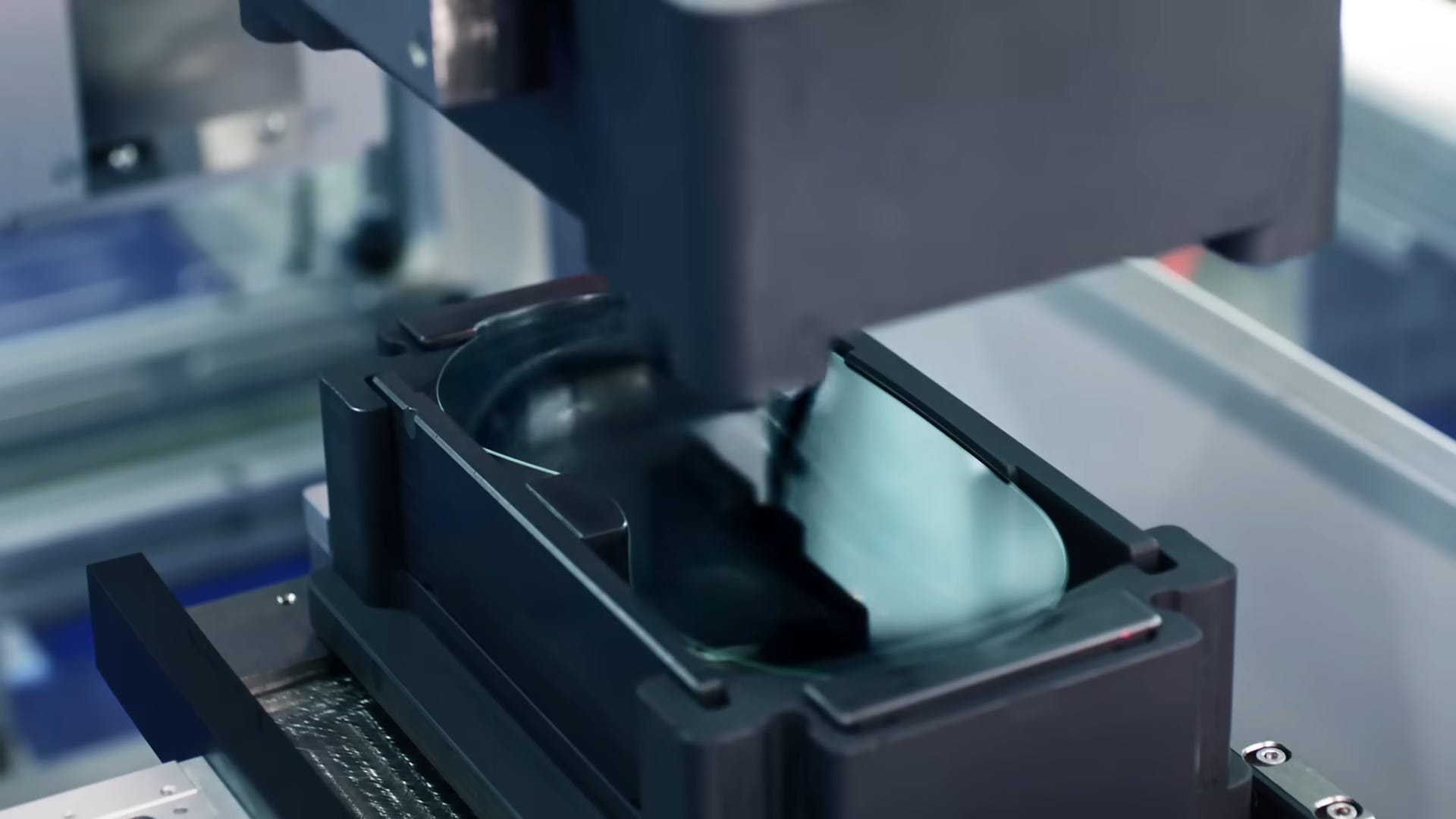
You may have noticed the 4 rectangular plates slid into the mold itself. Rather than make a single “perfect” mold, it’s generally a better idea to make it modular with removable inserts to help dial in the optimal location of the glass blanks. It may also sometimes be a wear surface can be swapped out cheaply and easily instead of replacing the entire expensive mold.

Delrin blocks are used on the ends of automated grabbers to contact the mold which can be fragile.
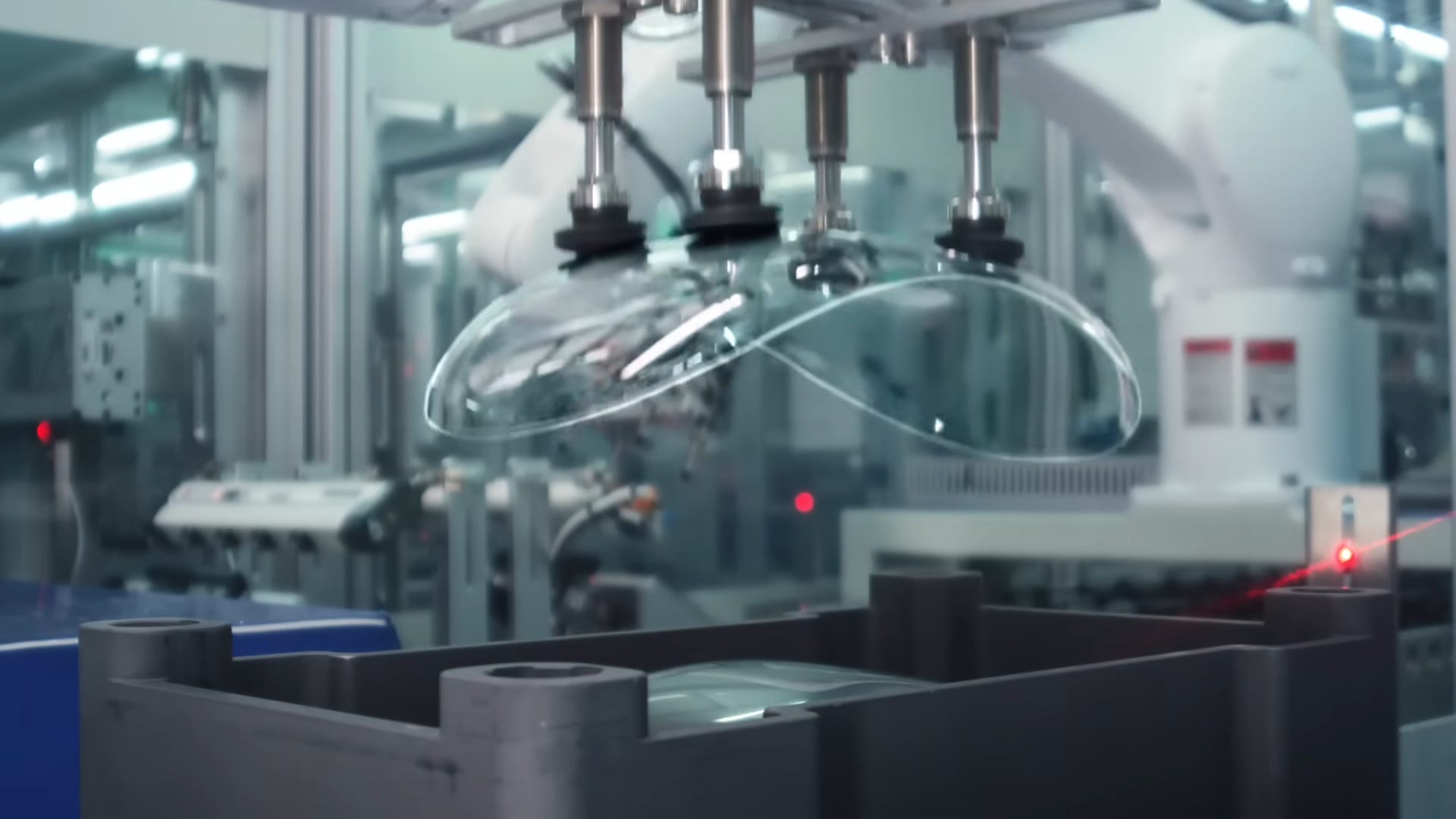
The final clip of this scene shows the top half of the mold, now inverted. The suction cups are larger to aid in grabbing onto the now curved surface. You can also see an identical fixture in the background that springs to life as this one moves on to the next operation.
You can also see the red light of what’s most likely a laser position sensor on the right side. These are used to confirm the part is in place to prevent errors in the automated manufacturing process. If it detects that something is missing, it can flag an alarm and call attention to an undesirable condition. It’s also designed with ample slot height to position it precisely where it’s needed for this or other setups.
Lens Finishing

The lenses are cleaned before being beveled and having the lens edge blackened before curing by heating elements in orange. Also note the use of more vacuum suction cups during the gorgeous beveling operation utilizing a 5-axis mill.
CNC Milling
After showing off some of their soft goods manufacturing prowess, they go on to showcase some very well done milling using a standard 3 axis mill.
Some background info: Milling vs Turning
Milling involves holding a part and contacting it with a spinning cutting tool.
Turning involves holding a cutting tool and contacting it with a spinning part.
Milling is good for hogging out profiles of parts, or plunge milling with tools like endmills or drills to sink the tool into the material.
Turning is terrific for moving massive amounts of material quickly, but only provided it’s in a symmetrical fashion about it’s center axis.
3 Axis vs 5 Axis (or more)
Most mills operate in 3 axes: X, Y, and Z. In other words, the cutting tool may move left/right, forewards/backwards, and up down. Occasionally some mills may move the table instead of the cutting head (or “spindle”), but a 3 axis mill still only has 3 axes of travel regardless of which is moving, the table or the spindle.
FYI: axis is singular, axes is plural, and pronounced axe-seize.

You might recall from the prior optic beveling operation that the cutting tool had 3 degrees of movement, but also the workpiece was also able to rotate AND tip or tilt fore and aft. This is a total of 5 axes of movement.

This is far more expensive a machine, more difficult to program, but has far greater capabilities. It’s able to cut at angles a traditional 3-axis mill cannot, more quickly, and in fewer operations. In manufacturing, minimizing the number of setups and operations is key to cutting costs. Many domestic machine shops charge between $60-90 per hour as rule of thumb. If you can reduce the amount of “touch time” required for a human to install or remove a part from a fixture, they’re operating at $1-1.50 per minute which adds up quickly.
@peteoxenham on Twitter/X had an excellent breakdown that everyone should read on the pneumatic workholding setup used here. The whole layout is a work of art, using multiple pneumatic tool holders activated in tandem to achieve maximum efficiency.
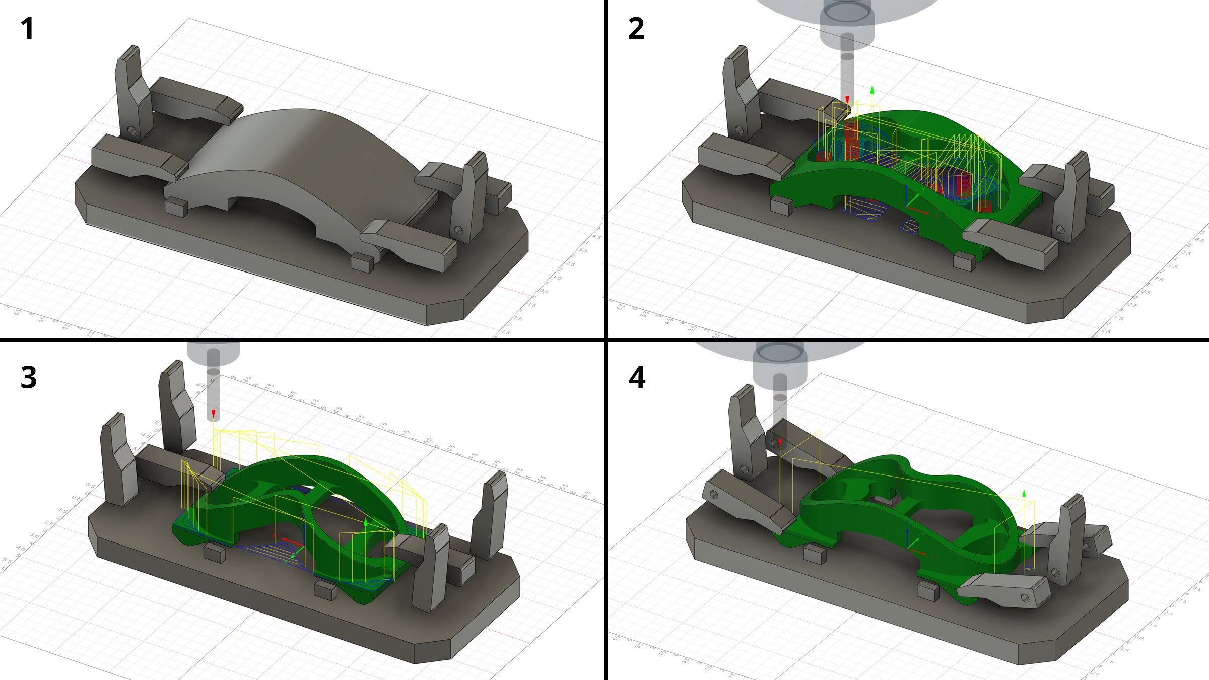
After the first operation removes some material, the pneumatic arms alternate to the middle ones so that the mill could machine new holding features, after which the arms would go back to the original configuration to continue all possible machining operations from this orientation. This is efficient as it is clever and people find joy in discovering and applying these efficiencies and the results can be seen in the decreased run-time per part.
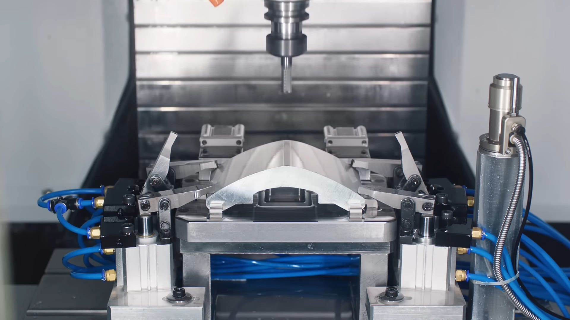

The streams of liquid you see is a form of coolant which is collected within the machine and resused. This both aids in removing chips as they’re cut from the part and reducing the amount of heat going to the tool cutter, which prolongs tool life and produces more consistent parts. Sharp tools cut better, and coolant helps keep them sharper longer.
It then cuts to a clip of a 5-axis machining operation called surf milling, or 3D surface milling, which is a painstaking method to carve radiused freeform surfaces into a part. It takes significantly longer than traditional milling because of the reduced cutter contact, but it permits you to machine shapes that typically require other manufacturing methods like casting or forging, each of which come with their own constraints and liabilities.

Note the pneumatic connectors indicating further automation in the securing of the workpiece, to be used in conjunction with robotic arms and other manufacturing wizardry to reduce the dependency on human machine operators.
Computer Controlled Polishing
The prior operation of surface milling will get a part pretty close to completion, but it still leaves a tell-tale surface finish that even tumbling with abrasive media won’t fully remove. This requires someone (or something) to rub it with an abrasive pad to remove the unsightly markings.

This can be done on machine by using progressively finer passes with the milling tool, but it reaches a point of diminishing returns at which point polishing with a pad is the obvious way to go.
Enter the most efficient deburring head on a robotic arm I’ve ever seen:
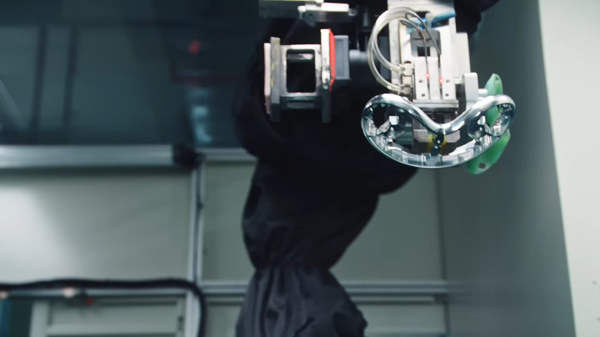
You have a polishing pad on the left side, the part itself on the bottom, and the top tooling fixture to secure the part on the right. The robotic arm is also draped in black cloth to protect it from any polishing media that tends to get everywhere. Or maybe it doesn’t and they just want to be secretive about the robotic arms they use.
Let’s look further:

The fixture the machined part it set upon looks to be made from Ultra High Molecular Density Polyethylene, or UHMD for short. This is an alternative material to Delrin in the creation of manufacturing fixtures. It’s often selected due to it’s…
High Abrasion Resistance - It will withstand repeated use for a long time
Low Coefficient of Friction - It’s self lubricating so it won’t stick to parts
Impact Resistance - Can withstand repeated shocks
Chemical Resistance - It’s resistant to many chemicals like solvents, acids, and polishing compounds
Non-Marring - It won’t leave marks all over your beautifully finished aluminum
Low Moisture Absorption - It’s stable and won’t swell in humid environments
Machinability - You can make accurate fixtures with this material in your mill
They also used locating pins to align the placement of the part so that the polishing routine would hit in all the right spots consistently.
The polishing pad looks like Melamine Foam, or the same material in your standard magic eraser.
Laser Ablation for Deburring
Aka Photoablation or Laser Blasting.
Ablate: to gradually remove material from or erode (a surface or object) by melting, evaporation, frictional action, etc., or erode (material) in this way.
"drying winds slowly ablate away the ice"
This is a relatively modern technique that’s not been widely adopted by any domestic manufacturers I’m familiar with. I’ve only seen documentation of such a process as far back as 2012 but it’s something that Apple’s seized upon and put to good use on even the Apple Watch.
I’ve used lasers for deep metal engraving for parts marking and putting aesthetic designs into parts, similar to how the grooves are cut into the Apple Watch’s crown, but using it for deburring is still a progressive utilization of a laser ability to “ablate” material for this purpose.
Here the headset frame is shown being picked by one set of tooling before being presented in another fixture for what appears to be a deburring operation.
You can again see laser positioning sensors confirming positive placement of the fixture to permit the next operation to continue. These sensors can operate individually or in tandem like the sensors in your garage door. Also kudos to the automation engineer or technician who so neatly wrapped his cables.

Precision Optical Alignment
Creating an optical design is one thing but it doesn’t mean much if you can’t align it. And that’s what I think they’re doing here. Blink and you’ll miss it.
The small reflective mirrors around the perimeter of the lens are most likely for alignment or metrology (measurement). They can serve several purposes:
Alignment: These markers can be used to align the glass correctly within the machine or with other components. This is particularly important for ensuring that subsequent manufacturing processes, such as cutting or assembly, are accurately executed.
Inspection and Quality Control: When placed under optical inspection equipment, these reflective markers can help machines quickly and accurately determine the orientation and position of the glass. Optical sensors can detect the reflected light from these markers to perform precise measurements.
Calibration: In processes that involve robotic arms or automated systems, these markers can be used for calibration. They help the system understand the exact dimensions and positioning of the glass piece.
Plastic Injection Molding
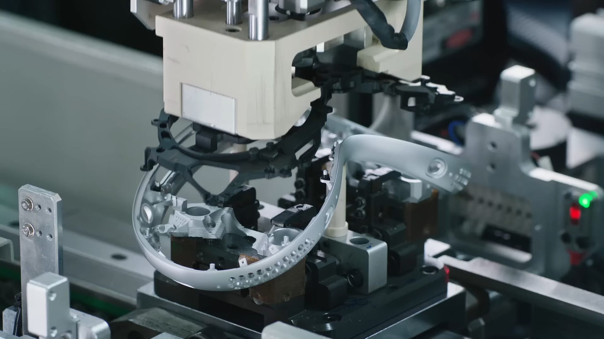
Here we can see a sub-frame being laid into place. The aluminum housing looks to have had some bushings installed to some of the threaded bosses but not others.
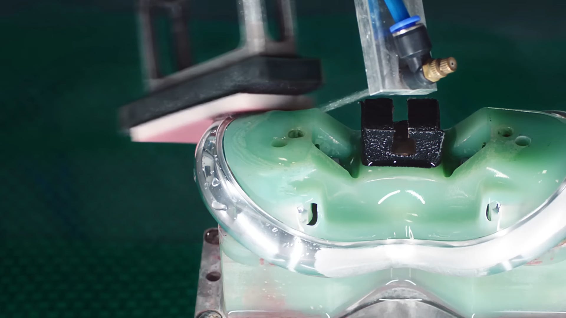
Laser Scanning Optical Metrology
The present state of the art in metrology involves lasers or vision systems to assess the geometry of part to determine its conformance to the desired specification, or to put more simply, is everything in place as it should be. That’s what this little blue laser is checking:
Let’s get a better look:
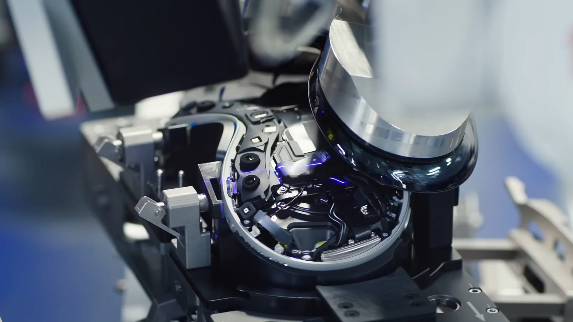
This single band of blue light is very probably a Keyence Laser Profiler, whose job is to insure that the assembled board is complete and in position. An improperly assembled board would likely play hell with the display moved off to the side and result in reduced yield rates. Here’s what one looks like without a fancy robot arm to elegantly wave the part.
Conclusion
Everything that Apple and Foxconn is doing represents the state of the art and setting the bar in high-precision, high-volume production. You can work in manufacturing for decades and only read about some of the techniques they use. I’ve worked with more companies than most and I can count on two fingers the number that has successfully utilized robotic arms.
The ability to combine all these disciplines goes to the heart of what makes Apple among the most successful manufacturers in the world. Any company can make a machine, but creating a machine that produces other machines at scale is an art few will ever see or appreciate.
“When you do things right, people won’t be sure you’ve done anything at all.”